
Wireless Servo Control with Motion
Wireless pan–tilt servo control with an IMU

This is another random project I picked up to get more familiar with embedded systems and hardware. I wanted to build something where one node could wirelessly control another, so I ended up using a pair of ESP32 boards as my nodes. For clarity, I’ll call the two nodes sender and receiver from here on.
As for what the sender would control, I went through a few ideas and eventually settled on a simple form of teleoperation. The concept is straightforward: the sender uses an inertial measurement unit to measure its motion and derive orientation, sends that orientation data wirelessly to the receiver, and the receiver reproduces the orientation using a pan–tilt servo mount.
Full code is available here on GitHub → ESP32 IMU Pan-Tilt
🎥 Here’s a quick demo (the full unedited version is at the bottom of this post):
Setup and Parts
Here are the hardware parts I used:
ESP32 LoRa V3 x 2 – one for the sender, one for the receiver
MG996R Servo Motors x 2 – mounted in a pan–tilt bracket
PCA9685 16-Channel Servo Driver – to control the servos
MPU6050 IMU – for motion sensing
Plus the basics: breadboards, jumper wires, and an external power supply for the servos.
🔌 Wiring Diagram
The wiring matches the exact pins used in the code.


📸 Hardware Photos


How it works
At a high level, the system is just passing the orientation data of one board to another and turning that into servo movement in real time.
Sender reads inertial measurements from the MPU6050 and derives orientation (yaw, pitch, roll).
It sends the orientation to the Receiver using ESP-NOW (a lightweight wireless protocol).
The Receiver takes those values and passes them to the PCA9685, which drives the pan–tilt servos.
That’s the basic flow. The rest of this post breaks down each component in more detail.
MPU6050: Orientation Sensing
The MPU6050 is an Inertial Measurement Unit (IMU) that combines a 3-axis accelerometer and a 3-axis gyroscope. Together, these sensors measure changes in acceleration and angular velocity.
The accelerometer tracks acceleration along the X, Y, and Z axes. When the IMU is lying flat and still, the only acceleration it sees is gravity, which appears entirely on the Z-axis. When tilted, gravity projects onto the X and Y axes as well, which lets you calculate pitch and roll through trigonometry.
Yaw is trickier. Because the MPU6050 doesn’t have a magnetometer, it has no absolute reference to Earth’s magnetic field. As a result, it cannot determine absolute heading. Instead, yaw is estimated by integrating the gyroscope’s angular velocity around the Z-axis over time. This gives us relative yaw (relative to the IMU’s starting position). However, relative yaw drifts because small gyro biases and noise accumulate during integration. Unlike pitch and roll, which the accelerometer can continuously correct using gravity as a reference, yaw has no such reference on the MPU6050 and therefore cannot self-correct.
The MPU6050 has an onboard Digital Motion Processor (DMP), which runs a sensor fusion algorithm directly on the chip. The DMP combines accelerometer and gyroscope data to produce processed orientation values, such as yaw, pitch, roll, or quaternions, and stores them in an internal FIFO buffer. The ESP32 can then fetch these results directly. By doing the computation on-chip, the DMP offloads processing that would otherwise run on the ESP32, which reduces both latency and power consumption.
Once the sender has these processed orientation values, it is then sent to the receiver.
Wireless Communication (ESP-NOW)
The ESP32 supports several wireless options: LoRa, Wi-Fi, Bluetooth, and ESP-NOW. LoRa is designed for long-range, low-bandwidth use cases, so it’s not suitable here. Wi-Fi and Bluetooth could work, but the ESP32 also has ESP-NOW. Unlike Wi-Fi or Bluetooth, ESP-NOW runs directly at the data-link layer, skipping most of the usual networking overhead and making it much lower latency.
In my setup, the sender reads the yaw, pitch, and roll values from the MPU6050, packs them into a data packet, and transmits them over ESP-NOW to the receiver. The receiver unpacks the values and forwards them to the servo driver, which moves the pan–tilt servos accordingly.
Pan-Tilt Servo Control
The pan–tilt mount uses two servos connected with a bracket, where one controls pan and the other controls tilt. Together, they provide two axes of control:
Pan = Yaw (rotation around the Z-axis)
Tilt = Pitch (rotation around the X-axis)
We’re not using roll here.
Technically, both servos could be wired directly to the ESP32, but that would take up multiple pins and make the wiring messy. Instead, I used a PCA9685 16-Channel Servo Driver, which controls up to 16 servos over I²C using just two pins on the ESP32.
After the receiver gets yaw, pitch, and roll values, it converts them into servo angles. The IMU provides these values in degrees: yaw and roll range over 360°, while pitch spans 180°. Since the servos can rotate only ~180°, I scale yaw into a 0–180° range and map pitch directly to 0–180°. Roll is ignored.
Servos don’t take degrees directly as they accept PWM signals. The PCA9685 generates these PWM signals, so the ESP32 only needs to map the scaled angles to the appropriate pulse widths.
Latency Measurement
To see how “real-time” the system actually was, I set up a simple GPIO pulse test by wiring a pin from the sender ESP32 to the receiver ESP32. The sender toggles the pin when it receives an MPU interrupt, which starts a timer on the receiver. When the receiver issues servo commands, it toggles the pin again and stops the timer. This way, I can measure latency entirely on one chip (receiver) without needing to synchronize clocks between boards.
Most latency samples clustered between ~2.0–2.5 ms, with occasional spikes up to ~5 ms. The median was ~2.1 ms, and 95% of samples came in under ~4.2 ms. A few ultra-low values (as low as 2 µs) showed up, but those are measurement artifacts rather than real latency.
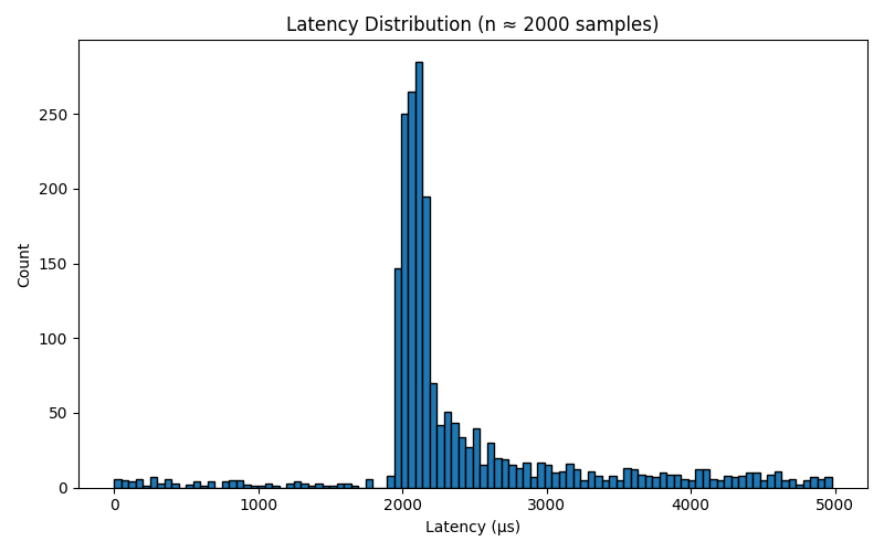
So in practice, the latency is about 2–3 ms. The real bottleneck here is mechanical: servos typically take 100–200 ms to move to a new position, so what you see is limited by how fast the motors can respond.
🎥 Here’s the full demo showing end-to-end responsiveness:
Things I’ve tried
At one point, I tried switching to the MPU9250, which adds a magnetometer for absolute yaw. In theory, this should have improved heading accuracy, but working indoors introduced a lot of magnetic interference, which actually made yaw drift worse. On top of that, I couldn’t find a well-supported library that exposed the DMP for the MPU9250.
That meant I had to read raw sensor data and run sensor fusion on the ESP32 itself. It worked, but the latency was noticeably higher because the sensor fusion had to run on the ESP32’s CPU rather than on-chip by the DMP. In the end, I went back to the MPU6050.
That’s all I’ve got for this one. Until next time…